Attenuation Calculator


Pi Attenuator


The Pi attenuator (Pi pad) is a specific type of RF attenuator circuit which resembles the shape of the Greek letter for Pi. The Pi attenuator consists of one series resistor and two parallel shunt resistors to ground at the input and the output.

FORMULAS

$$ R_1 = Z_0 \left( \frac{10^{\frac{A_{dB}}{20}} + 1}{10^{\frac{A_{dB}}{20}} - 1} \right) $$

$$ R_2 = \frac{Z_0}{2} \left( 10^{\frac{A_{dB}}{20}} - \frac{1}{10^{\frac{A_{dB}}{20}}} \right) $$
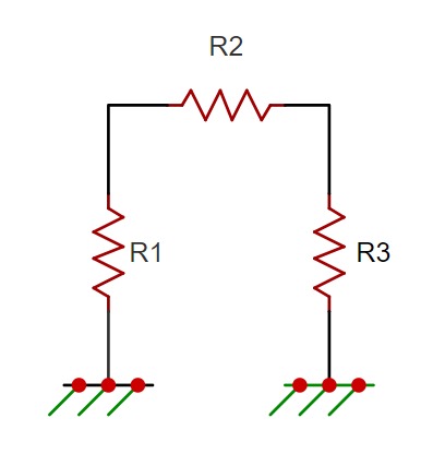
Circuit Diagram

Bridged-Tee Attenuator


A bridged-T attenuator uses resistors in a specific configuration to reduce signal amplitude while maintaining impedance matching, ensuring minimal signal reflection and power loss in RF circuits.

FORMULAS

$$ R_1 = Z_0 \left( 10^{\frac{A_{dB}}{20}} - 1 \right) $$

$$ R_2 = Z_0 \left( \frac{1}{10^{\frac{A_{dB}}{20}} - 1} \right) $$
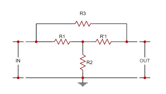
Circuit Diagram

Tee Attenuator


A T attenuator consists of three resistors in a T configuration, used to reduce signal amplitude while maintaining impedance matching, minimizing signal reflection and power loss in RF and audio applications.

FORMULAS

$$ R_1 = Z_0 \left( \frac{10^{\frac{A_{dB}}{20}} - 1}{10^{\frac{A_{dB}}{20}} + 1} \right) $$

$$ R_2 = 2Z_0 \left( \frac{10^{\frac{A_{dB}}{20}}}{10^{\frac{A_{dB}}{10}} - 1} \right) $$
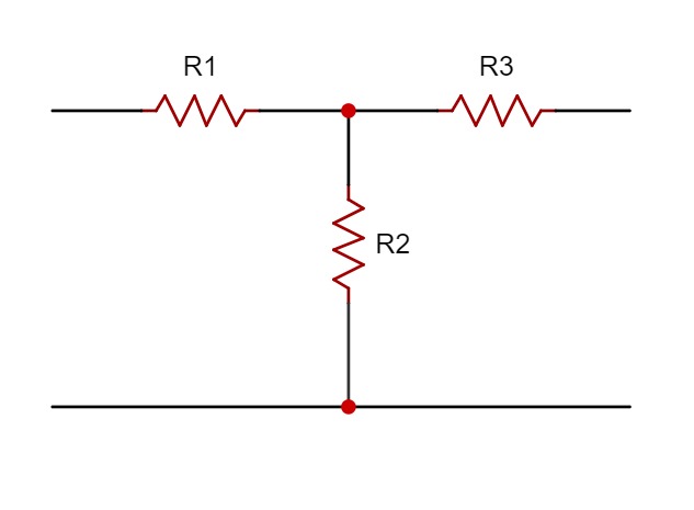
Circuit Diagram
Copyright © 2023 Invootechnica Global Pvt. Ltd. All rights reserved.